


Fiber Optic Tech
The Working Principle and Characteristics of OTDR
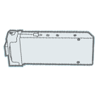
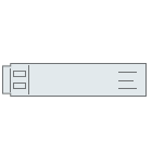
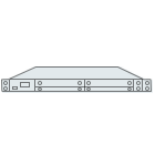
Optical Time Domain Reflectometer (OTDR) is an important tool for testing the integrity of fiber optic cables, which can be used to uate the length of fiber optic cables, measure transmission and connection attenuation, and detect the of faults in fiber optic links. Based on these functions, it is usually used in the maintenance and construction of fiber optic cables. Additionally, the OTDR is most effective when testing long cables or cable installations with connectors, illustrating where the cable is terminated and confirming the quality of the fibers, connections and connectors.
How does OTDR work?
Compared with those signal sources and power meters that directly measure the loss of optical cable equipment, OTDR works indirectly. By replicating the transmitter and receiver of a fiber optic transmission link, the source and meter enable good correlation of measurements to actual system losses. However, OTDR measures the loss indirectly by using a unique optical phenomenon "backscattered light" to measure reflected light from a connector or the end of a cleaved fiber.
During the OTDR test, the instrument injects a higher power laser or fiber light source pulse into the fiber from one end of the fiber optic cable, and uses the OTDR port to receive the returned information. As the light pulse travels through the fiber, some scattered reflections will return to the OTDR. Only the returned useful information can be measured by the OTDR detector, which acts as a time or curve segment of the fiber at different s. Distance can be calculated by noting the time it takes for the signal to travel from transmission to return, and the speed of transmission in the fiber.
Working Principle of OTDR
OTDR uses Rayleigh scattering and Fresnel reflection to measure the characteristics of optical fiber. Rayleigh scattering refers to the irregular scattering that occurs as an optical signal travels in an optical fiber. OTDR measures only the scattered light at the OTDR port. The backscatter signal shows the degree of attenuation (loss/distance) of the fiber and will be traced as a downward curve illustrating the reduction in backscattered power. This is because both the transmitted signal and the backscatter loss are attenuated.
The Rayleigh scattering power is related to the wavelength of the transmitted signal: the shorter the wavelength, the stronger the power, which means that the 1310nm signal trace will generate higher backscattering losses than the 1550nm signal.
In the higher wavelength region (over 1500nm), Rayleigh scattering will continue to decrease, and another phenomenon called infrared attenuation will increase, resulting in an increase in the overall attenuation value. Therefore, the 1550nm wavelength has the lowest attenuation, which justifies why it is the long-distance communication wavelength. Similarly, the OTDR with a wavelength of 1550nm also has low attenuation, so it can also be used for long-distance testing.
Fresnel reflections belong to the category of discrete reflections caused by a single point throughout the fiber. These points are the result of varying inverse coefficient elements such as glass and air gaps. At these points, strongly backscattered light will be reflected back. Therefore, OTDR uses the information of Fresnel reflection to locate connection points, fiber terminations and breakpoints.
OTDR Blind Spot Solution
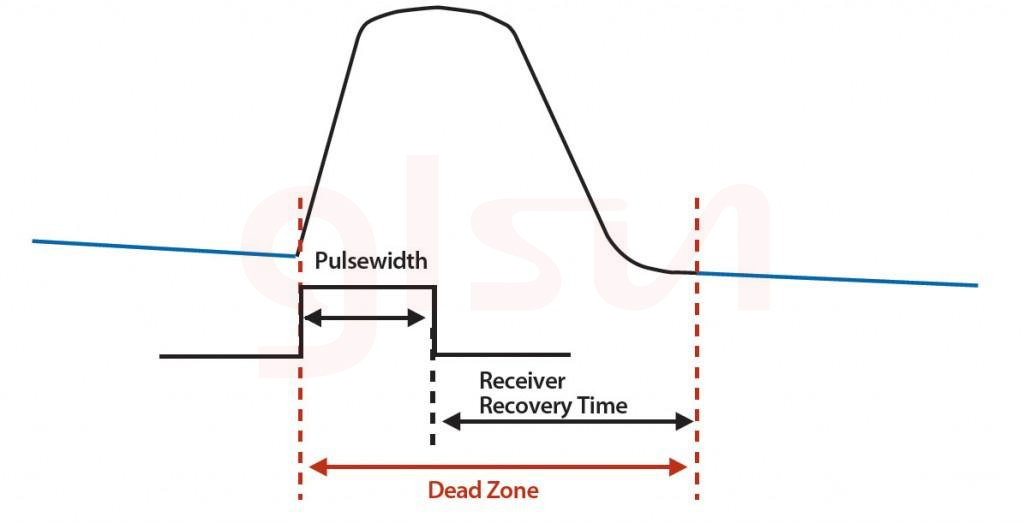
Let's take a look at an important OTDR specification, which originates from Fresnel reflection, called "dead zone". Basically, there are two types of dead zones: event and decay. They are all expressed in distances that vary according to the power of those reflections. The dead zone is the length of time that the detector is temporarily obscured by a large amount of reflected light until it recovers and can read light again. When an OTDR is working, time is converted to distance, so more reflections cause the detector to have more time to recover, resulting in a longer dead zone. The dead zone limits the operation of OTDR to a great extent, making it impossible to locate and solve faults. The figure below shows the dead zone of an OTDR.
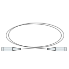
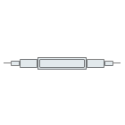
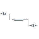
Blind spots seem to be a problem when testing with an OTDR, however, adapting a visual fault locator (VFL) can be an effective solution to this problem. It is a supplement to OTDR in cable troubleshooting because it successfully covers the range that OTDR cannot monitor due to dead zone. The visual fault locator is designed with visible laser and universal adapters (such as FC, SC and ST, etc.), which help to locate faults on fiber optic links easily. For example, locate breaks, bent or cracked fiber optic cables, and locate faults in ODTR dead zones. Higher power visual fault locators can spot fiber breaks in simplex cables or high losses around connectors. If light escapes at one break, it will be visible through the fiber's jacket. This is especially useful in finding cable faults near the end of the cable, where the OTDR's dead zone limits its ability to resolve faults. At the same time, VFL can also be used to find cracked optical fibers or bad connectors that cannot be found by OTDR.
In short, the OTDR tester is essentially a kind of optical radar. By emitting a bright flash, it measures the strength of the echo or reflection. Therefore, OTDR is mainly used for optical fiber installation and maintenance services of access network and user network. Calculations are used to display trajectories and do some mathematical derivation.


