


Fiber Optic Tech
The Intelligent Optical Communication Test Platform Solution
Building an efficient and automated optical communication test platform starts with powerful components. In the rapidly evolving landscape of optical communication, the demand for higher bandwidth, lower latency, and increased reliability is constant. Meeting these stringent requirements necessitates sophisticated testing methodologies and advanced equipment. An intelligent optical communication test platform, meticulously designed with high-performance modules, is not just an advantage but a necessity for modern manufacturing and research. This article delves into the core components that form the backbone of such a platform, exploring how each contributes to an integrated solution that significantly boosts testing efficiency and data accuracy, thereby driving the future of smart optical manufacturing.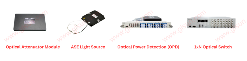
The Cornerstone: ASE Light Source – Illuminating Precision
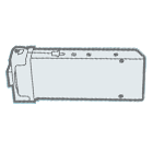
The ASE (Amplified Spontaneous Emission) light source is a foundational element of any comprehensive optical communication test platform. Its primary function is to deliver a stable, broadband optical output, providing the high-quality optical signals essential for accurate and repeatable testing. Unlike traditional narrow-band sources, an ASE light source offers a wide spectral range, making it ideal for characterizing a diverse array of optical components and systems, from optical fibers and connectors to filters and multiplexers/demultiplexers.
The stability of an ASE light source is paramount. Fluctuations in output power or spectral characteristics can introduce significant errors into measurements, compromising the integrity of test results. Modern ASE sources employ advanced control mechanisms, including temperature stabilization and current regulation, to ensure remarkably consistent output over extended periods. This stability is crucial for long-duration tests, such as those for component aging or system endurance, where even minor drifts can invalidate an entire test run.
Furthermore, the broadband nature of ASE light sources is invaluable for spectral measurements. When coupled with an optical spectrum analyzer (OSA), an ASE source enables precise characterization of the spectral response of optical components, including insertion loss, return loss, and wavelength-dependent attenuation. This capability is vital for assessing the performance of wavelength-division multiplexing (WDM) components, where accurate spectral profiling is essential for system interoperability and performance. The high power output often achievable with ASE sources also allows for testing components with significant insertion loss, expanding the range of applications and scenarios that can be effectively addressed. In essence, the ASE light source is more than just a signal generator; it is the reliable, broadband illuminator that underpins the precision and reliability of the entire test ecosystem.
Precision Control: The Optical Attenuator – Sculpting the Signal
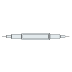
Following the light source, the optical attenuator plays a critical role in shaping and controlling the optical signal for various testing scenarios. With its capability for precision power control, the optical attenuator ensures consistent and reliable testing conditions, mimicking real-world operating environments and allowing for accurate characterization of component performance under different power levels.
Optical attenuators can be broadly classified into fixed and variable types. While fixed attenuators provide a constant level of attenuation, variable optical attenuators (VOAs) are indispensable for intelligent test platforms due to their dynamic adjustability. VOAs allow engineers to precisely set the optical power level incident on a device under test (DUT), enabling a wide range of experiments, such as characterizing the power handling capabilities of components, determining the dynamic range of receivers, or simulating signal degradation over long transmission distances.
The precision of an optical attenuator is measured by its attenuation range, step size, and accuracy. High-performance attenuators offer a broad attenuation range, typically from 0 dB to 60 dB or more, with fine step sizes, often as low as 0.01 dB. This granular control is crucial for applications requiring highly precise power adjustments, such as bit error rate (BER) testing, where even small variations in received power can significantly impact results. Furthermore, the repeatability and linearity of the attenuation are vital to ensure that measurements are consistent and accurate across the entire attenuation range.
Modern optical attenuators often feature integrated power monitoring capabilities, allowing for real-time verification of the attenuated power level. This feedback loop enhances the accuracy of testing by ensuring that the desired power is consistently delivered to the DUT, compensating for any drifts in the light source or other system variations. The ability to programmatically control the attenuation levels also facilitates automated test sequences, where power levels can be swept or stepped through a predefined range, further improving test efficiency and throughput. In essence, the optical attenuator is the precision instrument that allows engineers to meticulously sculpt the optical signal, ensuring that components are tested under the exact conditions required for comprehensive and reliable characterization.
Agile Routing: The 1×N Optical Switch – Navigating Complexity
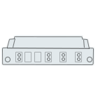
The 1×N optical switch is a pivotal component in an intelligent test platform, enabling flexible multi-channel routing for automated test workflows. In complex optical systems, testing often involves connecting a single instrument to multiple devices under test (DUTs) or routing signals from multiple sources to a single analyzer. Manually reconfiguring optical connections for each test scenario is time-consuming, prone to error, and limits the throughput of the test process. This is where the 1×N optical switch excels.
A 1×N optical switch takes a single input optical signal and routes it to one of N output ports, or vice-versa, depending on the switch configuration. This capability is fundamental for automating test sequences involving multiple components or measurement points. For instance, in a production environment, a single optical spectrum analyzer can be used to characterize the spectral performance of numerous optical filters on a production line by sequentially connecting them through the optical switch. This eliminates the need for manual cable swapping, drastically reducing test time and improving overall efficiency.
Beyond simple routing, advanced optical switches offer features such as low insertion loss, high isolation between channels, and fast switching times. Low insertion loss is crucial to minimize signal degradation as it passes through the switch, preserving the fidelity of the test signal. High isolation ensures that signals from unselected channels do not interfere with the active channel, maintaining the accuracy of measurements. Fast switching times are essential for high-throughput testing, especially in automated environments where hundreds or thousands of switching operations might occur during a single test run.
The programmable nature of 1×N optical switches allows for seamless integration into automated test executive software. Test s can control the switch configuration, enabling the creation of complex test sequences that can run unattended. This automation capability is vital for both research and development (R&D), where exhaustive characterization of prototypes is required, and for manufacturing, where high-volume testing with consistent quality is paramount. By providing agile routing capabilities, the 1×N optical switch transforms a collection of individual instruments into a cohesive, automated test system, significantly enhancing flexibility and accelerating the testing process.
Verifying Performance: The Optical Power Detector – Monitoring with Precision
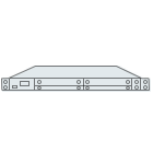
The optical power detector is the eyes of the intelligent test platform, allowing real-time power monitoring and significantly enhancing measurement accuracy. While the light source generates the signal and the attenuator controls its intensity, the power detector provides the crucial feedback loop, quantifying the optical power at various points within the test setup and at the DUT.
Optical power detectors come in various forms, including photodetectors, power meters, and integrated power monitoring modules. Their fundamental role is to convert optical power into an electrical signal that can be measured and displayed. Key performance parameters for optical power detectors include wavelength range, power measurement range, accuracy, and response time. A wide wavelength range ensures compatibility with various optical communication windows (e.g., 850 nm, 1310 nm, 1550 nm), while a broad power measurement range allows for characterization of both high-power and low-power signals.
The accuracy of the power detector is paramount. Calibration against traceable standards is essential to ensure that the measured power levels are reliable and consistent across different instruments and test environments. Real-time power monitoring provides immediate feedback on the stability of the light source, the effectiveness of the attenuator, and the optical loss or gain of the DUT. This instantaneous feedback is invaluable for troubleshooting, identifying subtle drifts, and ensuring that test conditions remain within specified tolerances.
In an automated test platform, optical power detectors are often integrated as modules or plug-in cards, allowing for synchronized measurements with other instruments. For instance, when characterizing the insertion loss of a component, power detectors can measure the input power and the output power simultaneously, providing an accurate and real-time calculation of the loss. In sophisticated systems, multiple power detectors can be strategically placed to monitor power at various points along the optical path, providing a comprehensive understanding of signal flow and degradation. This continuous monitoring capability not only enhances the accuracy of individual measurements but also contributes to the overall stability and reliability of the entire test platform, ultimately leading to more robust and trustworthy test results.
The Symphony of Integration: Driving the Future of Smart Optical Manufacturing
Integrating all these modules—the ASE light source, optical attenuator, 1×N optical switch, and optical power detector—is where the true power of an intelligent optical communication test platform is unleashed. Each component, while powerful on its own, achieves its full potential when seamlessly orchestrated within a unified system. This integration transcends the sum of its parts, creating a dynamic and highly efficient test environment capable of addressing the most demanding challenges in optical communication.
The synergy begins with automated control. Modern test platforms are driven by sophisticated software that orchestrates the functions of each module. This allows for the creation of complex, multi-step test sequences that run autonomously, without manual intervention. For example, a single test can:
1. Turn on the ASE light source and set its power.
2. Configure the optical attenuator to sweep through a range of power levels.
3. Use the 1×N optical switch to connect to multiple DUTs sequentially.
4. Utilize the optical power detector to record real-time power measurements for each DUT at each attenuation level.
5. Log all data, perform analysis, and generate comprehensive reports.
This level of automation dramatically boosts testing efficiency and throughput. Manual setup and measurement are replaced by rapid, repeatable, and error-free automated processes. In a manufacturing setting, this translates directly to faster production cycles, reduced labor costs, and improved product quality due to more thorough and consistent testing. For R&D, it means engineers can spend less time on repetitive tasks and more time on design innovation and data interpretation.
Furthermore, integration enhances data accuracy and reliability. By eliminating manual intervention, the platform minimizes human error, a common source of inaccuracies in traditional test setups. The precise control and real-time monitoring capabilities of the integrated modules ensure that test conditions are consistently maintained, leading to highly repeatable and trustworthy results. Advanced software can also incorporate statistical analysis and anomaly detection, further refining the quality of the data and providing deeper insights into component and system performance.
The future of smart optical manufacturing is intrinsically linked to such intelligent test platforms. As optical communication technologies continue to advance, demanding ever-higher performance and complexity, the need for highly efficient, accurate, and automated testing will only grow. These integrated platforms are not just tools for measurement; they are catalysts for innovation, enabling the rapid development and deployment of next-generation optical devices and systems. By embracing this holistic approach to testing, the optical communication industry can continue to push the boundaries of what's possible, driving advancements in data transmission, networking, and beyond. This intelligent integration truly embodies the essence of "Industry 4.0" in the optical domain, paving the way for fully automated, data-driven, and highly optimized manufacturing processes.


