


Fiber Optic Tech
The Development of All Optical Cross-Connect Technology
ROADM (Reconfigurable Optical Add-Drop Multiplexer) can realize multi-dimensional, large-capacity wavelength-level scheduling, has the advantages of low latency and low power consumption, and meets the networking needs of trunk lines, metropolitan areas and data center interconnections. As the dimension increases, the number of internal fiber connections in a ROADM site increases dramatically, resulting in long startup and maintenance time, error-prone, and significant increases in floor space and power consumption. Optical Cross-Connect (OXC) optimizes and improves the problems that arise in the use of ROADM. It uses an all-optical non-blocking cross-connect optical backplane, cooperates with highly integrated optical circuit boards and optical add-and-drop circuit boards to achieve plug-in board is used for fiber connection, which avoids complicated internal fiber connection and improves the efficiency of startup and maintenance. The OXC single cabinet can realize 32-dimensional cross-scheduling to save space. Since 2018, OXC technology has been widely used by operators such as China Mobile, China Telecom, and China Unicom.
OXC Composition and Key Technologies
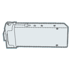
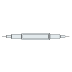
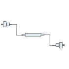
OXC mainly includes optical backplanes, optical circuit boards and optical add/drop circuit boards, involving key technologies such as optical backplanes, high-density optical connectors, 1×N WSS (wavelength selective switch), and M×N WSS. Optical backplanes include flexible optical backplanes and high-density connectors. OXC's optical add and drop boards are divided into two types: optical add and drop boards that support CDF (Colorless, Directionless, Flexgrid) and CDCF (Colorless, Directionless, Contentless, Flexgrid), as shown in Figure 1 and Figure 2. The former uses TWIN 1×N WSS, which does not support competition and has nothing to do with it; the WSS and optical amplifier are integrated, occupying 1 slot, and can realize 32-channel service up and down, scheduling through the high-density connector of the single board and the optical fiber connection of the optical backplane. to any light direction. The latter uses M×N WSS and occupies 2 slots. It can realize 8/16 dimensions, 48 waves of business up and down, and supports 8/16 dimensions regardless of competition.
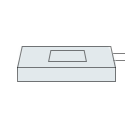
OXC's optical line single board highly integrates WSS, optical amplifier, OP, OSC, and OTDR functional modules. One optical line single board occupies one slot and implements corresponding functions in one optical direction. The optical circuit board is connected to the optical backplane through high-density connectors, and a set of wavelengths can be scheduled to any optical direction or to any optical add/drop board for service add/drop (Figure 3).
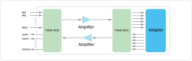
Figure 1 Optical add-and-drop circuit board (CDF)
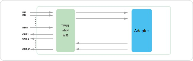
Figure 2 Optical add and drop board (CDCF)
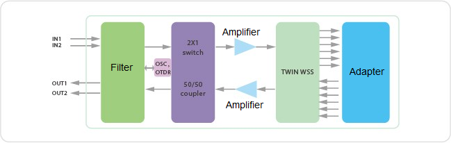
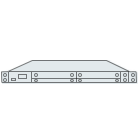
Figure 3 Optical circuit board
Optical Backplane
The ROADM schedules different light directions and connects the local upstream and downstream through the optical fiber port of the WSS single board panel. For 9-dimensional, 20-dimensional and 32-dimensional ROADM, the number of connected fibers is 81, 400 and 1024 respectively. In order to solve the problems of complex, error-prone, and difficult maintenance of a large number of optical fiber connections, OXC adopts optical backplane technology. Convert the internal fiber connections between optical ports on ROADM boards into high-density interconnection fibers on the optical backplane. The internal connected fibers are divided into multiple groups and routed through an optical fiber routing machine, and then packaged into flexible sheets to form a flexible optical backplane that supports unobstructed optical fiber connections. Taking 32-dimensional OXC as an example, the optical fibers need to be divided into 32 groups, each group has 64 cores. Optical fibers need to be left for optical performance monitoring and backplane insertion loss detection. In fact, there are more than 64 cores. At present, the production and processing of 32-dimensional flexible optical backplanes is very mature, and many domestic and foreign manufacturers have mass production and delivery capabilities. At the same time, the industry has the production capacity of higher-dimensional flexible optical backplanes to meet the needs of OXC's development to higher dimensions.
High Density Connector
The optical backplane is connected to the optical line board and the optical add/drop board through high-density connectors.
OXC's optical connector must have two characteristics. The first is high density. For 16-dimensional OXC optical connectors, at least 32-core optical fibers are needed, and for 32-dimensional OXC, at least 64-core optical fibers are needed to ensure full interconnection of all optical boards in the OXC. In fact, connecting optical fibers must be reserved for monitoring, detection, loopback and other functions, and more optical fiber cores are required. Second, it can be blind-mated, which requires the connector to have high docking accuracy, reliability for multiple insertions and extractions, flexible design, and low insertion loss.
Standard MT connectors can already realize 24-core optical fiber packaging, and multiple groups of MTs form an array. Combined with flexible design, backplane sockets, single-board sockets, etc., a complete OXC optical connector can be realized. In addition, non-contact connectors with improved end-face coating processes are also being developed, which is expected to further increase capacity and improve performance.
WSS Wavelength Selective Switch WSS
The core components of optical add and drop single boards and optical circuit boards are 1×N WSS and M×N WSS. Related technologies mainly include LC Array (Liquid Crystal Array), MEMS (Micro-Electro Mechanical System) and LCoS ( Liquid Crystal on Silicon) and silicon photonic-based micro-ring resonators MRR (Micro-Ring Resonator) and MZI (March-Zehnder Interferometer).
WSS based on LC array changes the polarization state of the incident light by adjusting the driving voltage. Birefringent prisms have different refractive indexes for light of different polarization states, thereby controlling the deflection angle of the outgoing light by changing the polarization state of the incident light. LC Array technology is mainly used for 1×9 and 1×20 WSS. When the number of ports increases, more LC cascades are required, making design and packaging difficult.
Based on MEMS WSS, each MEMS mirror can be controlled individually. By changing the control voltage, the rotation angle of the MEMS mirror can be controlled, thereby changing the reflection angle of the incident light and entering different output light ports to achieve wavelength selection. MEMS can be used in high-port WSS and M×N WSS. Because the spacing between mirrors is too large and the duty cycle is low, spectral depressions will occur during continuous spectral operation. Flexible grids cannot be realized, and the application scenarios are limited.
LCoS-based WSS implements a liquid crystal driving circuit based on CMOS transistor design technology on a silicon substrate. There is a two-dimensional array of pixels on the substrate, and each pixel can change the voltage independently through the driving circuit, thereby changing the phase of the liquid crystal on the pixel. Adjusting the phase delay of adjacent pixels separately enables free switching of optical signals between ports. LCoS technology has a higher fill ratio factor and higher pixel resolution. It has been used to produce high-port 1×N WSS. It is more suitable for producing M×N CDCF WSS that supports flexible rasters and has become mainstream.
Based on the WSS of the micro-ring resonator (Micro-Ring Resonator), the SOI waveguide can realize a micro-ring structure with a small radius due to the large refractive index difference. By adjusting the resonance state of the micro-ring, the add and drop of the specified wavelength can be achieved. In recent years, relevant research has proposed some solutions to key issues such as the free spectrum region (FSR) range, hitless lossless adjustment, and polarization independence in the MRR-based WSS scheme. It is expected to further solve related issues such as processing accuracy and control complexity. Achieve breakthroughs in industrialization. In addition, there are also filter designs based on a combination of MZI and microrings or solely based on MZI for wavelength selection. It will also take some time for the technology to mature.


