Fiber Optic Tech
Technical Parameters of Optical Transceiver Modules
Optical Transmitter Technical Parameters
Optical Power: The optical power value of the optical transmitter (dBm) is determined by the optical power sent by the laser, and the optical power plays a decisive role in the transmission distance of the optical signal. Theoretically, the greater the optical power, the farther the optical signal transmission distance (long relay distance), but in fact, the greater the optical power, the life of the laser will be greatly affected.
Currently, the more commonly used laser types are FP and DFP, and of course there are several other types, such as VCSEL, EML, etc.; LED light-emitting diodes can also be used as light sources, but they are generally used for low speed (155M), short distance (2KM) occasions.
Both FP and DFB are edge-emitting, with different resonant cavity structures. They are mostly used for single-mode medium and long-distance transmission. These two lasers can be classified into the same category. The main difference between the two is that the DFB laser has a built-in isolator that can filter out Unwanted wavelengths reduce dispersion, so they can be transmitted farther, but are more expensive.
LED and VCSEL (vertical cavity surface emitting laser) both are surface-emitting, with different resonant cavity structures. They are mostly used for multi-mode short-distance transmission, and the main transmission wavelength is 850nm;
EAM (EML), electroabsorption modulated laser, optoelectronic integrated device, composed of TEC cooler, laser diode, EA modulator, backlight detection diode, thermistor, etc., often used for ultra-long distance transmission, and the price is more expensive.
In optical fiber communications, semiconductor laser diodes dominate, which are mainly used in long-distance and large-capacity (high code rate) optical fiber communication systems, followed by light-emitting diodes, which can be used in short-distance, low-capacity systems or used in simulation systems.
Spectral Width: The narrower the spectral line width of the light source device, the better. The narrower it is, the smaller the light dispersion caused, and the more conducive it is to large-capacity transmission.
Extinction Ratio: The ratio of the “1” code optical pulse power to the “0” code optical pulse power. Usually it is better to have a larger extinction ratio of the optical transmitter.
Side Mode Suppression Ratio (SMSR): For an optical transmitter using a single longitudinal mode laser (DFB), the ratio of the main longitudinal mode optical power to the maximum side mode optical power is SMSR>30dB, and the main optical power is more than 1000 times the maximum side mode optical power.
Comparative Analysis of FP Laser and DFB Laser
The dispersion of FP laser is larger than that of DFB laser, and it is mainly used for medium-distance transmission of 20KM~40KM. The dispersion of DFB laser is small, and it is mainly used for long-distance transmission of more than 40KM.
FP laser: poor spectral characteristics, multiple side modes, and dispersion problems. It can only be used for medium and low speeds (speeds below 1G~2G) and short-distance applications (less than 10KM).
OC-48 rate, used for 2KM products (OC-48 rate: 48 times optical carrier, transmission speed is 2488.32Mbit/s, 48 times the basic rate of SONET optical cable OC-1.)
1G rate, usually used in 10KM products.
155M rate, usually used in 40KM products.
DFB laser: The spectral characteristics are very good and can avoid the influence of dispersion in long-distance transmission. Therefore, it is widely used in long-distance and high-speed applications.
OC-48 rate, usually used in 10KM products
1G rate, usually used in 40KM products.
155M rate, usually used in 80KM products.
The laser is the core device in optical transceiver module. It injects current into the semiconductor material and emits laser light through the photon oscillation and gain of the resonant cavity.
Currently, the most commonly used lasers are FP and DFB lasers. The difference between them is the semiconductor material and resonant cavity structure. DFB lasers are much more expensive than FP lasers. Optical transceiver modules with a transmission distance within 40KM generally use FP lasers; optical transceiver modules with a transmission distance over 40KM generally use DFB lasers.
Optical Receiver Technical Parameters
Responsiveness: The first photocurrent generated when a unit optical power signal is incident on a photodiode. It is determined by its quantum efficiency. The quantum efficiency of a high-quality photodiode can reach 90%.
Response Time (or frequency characteristics): PIN photodiode response time is generally about 1ns.
Junction Capacitance: affects the response time of the PIN photodiode and plays a decisive role in the sensitivity of the optical receiver. The smaller the better.
Dark Current: The main source of additional noise in photodiodes, which is mainly composed of body current determined by the structure and dark current caused by the process.
Since PIN photodiodes have no multiplication effect, their dark current is very small, and the additional noise they generate is also very low, so their impact on the sensitivity of the optical receiver is not significant.
There are two major types of optical receiving devices (photodetection devices) used in optical communications, namely PIN photodiodes and APD avalanche photodiodes.
APD (Avalanche Photodiode) is a high-sensitivity photodetector that uses the avalanche multiplication effect to double the photocurrent. It can increase the receiving sensitivity by 6~10dBm.
The main difference between the two is that PIN photodiodes have no photomultiplier effect (amplification), while APD avalanche diodes have photomultiplier effects (amplification).
Since APD itself has an amplification effect, it is equivalent to an amplifier and can amplify the detected weak signals. Therefore, the receiving sensitivity is higher than that of PIN, which results in a higher price than PIN. However, there is also a disadvantage that due to the amplification effect, the purity of the optical signal is very high (because the amplified impurity optical signal will produce a lot of noise, which will have a great impact on the sensitivity of the optical receiver). Therefore, APD The quality requirements for the entire optical module are higher.
The Main Technical Indicators of Optical Receiver
Bit Error Rate: The bit error rate in optical fiber communication systems is low, mainly due to various noises and interference in the system.
Sensitivity: The minimum input optical power required by the receiver under the condition of ensuring the required error bit rate (dBm).
The sensitivity of the optical receiver is mainly determined by the noise of the optical receiver, and sometimes the influence of inter-symbol crosstalk must also be considered. Noise mainly comes from detector and amplifier noise.
Sensitivity is the most important performance indicator of an optical receiver, and its concept is linked to the bit error rate. In the digital optical fiber communication system, the optical signal at the receiving end is detected, amplified and equalized, and then judged and regenerated. Due to the presence of noise, the received signal may be misjudged. The probability that a received symbol is incorrectly judged is called the bit error rate. Sensitivity refers to the minimum optical power that an optical receiver needs to input to ensure a given bit error rate. Sensitivity can be expressed in terms of the lowest equilibrium energy required per optical pulse, but more often it is expressed in terms of the lowest average optical power (W or dBm).
Sensitivity indicates the ability of an optical receiver to receive weak light signals when adjusted to its lowest state. Increasing sensitivity means being able to receive weaker optical signals, that is, the higher the receiving sensitivity, the farther the relay distance.
Dynamic Range: During long-term use, the optical power of the optical receiver may change. Below the lower limit of this dynamic range (i.e. sensitivity), excessive bit errors will be generated; above the upper limit of this dynamic range (over"" power of the receiver), excessive bit errors will also be generated during decision making. The difference between the minimum output optical power (dBm) and the maximum input optical power (dBm) of the receiver while ensuring the bit error rate index of the system.
Saturated Optical Power Value: The maximum optical power that can be detected by the receiving end of the optical module, generally -3dBm. When the received optical power is greater than the saturated optical power, bit errors will also occur. Therefore, bit errors will occur when testing optical modules with high transmit optical power without attenuation and loopback.
Optical Eye Diagram: Send the (NRZ code) optical signal output by the optical transmitting module into the sampling oscilloscope, and you can observe the "eye diagram" of the optical signal waveform.
The quality of the optical pulse signal can be observed on the optical eye diagram. The rise time, fall time, overshoot and undershoot of the optical pulse waveform should be controlled to avoid reducing the receiving sensitivity. The optical pulse shape characteristics are given by the eye diagram template, which has been specifically specified in the standards of optical communication systems.
Relationships Among Optical Power, Sensitivity, Attenuation and Transmission Distance.
Optical power is represented by Pout, sensitivity is represented by Pin, transmission distance is represented by D (distance), and attenuation is represented by A (attenuation).
In general, in addition to the fiber transmission distance attenuation, the light attenuation also includes the attenuation of the light outlet connector, but it is relatively small (about 0.5dB) and can be ignored.
Different wavelengths of light have different attenuation degrees: the light attenuation degree of the 1310nm wavelength is about 0.35dB/KM; the light attenuation degree of the 1550nm wavelength is about 0.25dB/KM-0.3dB/KM. Note: Increasing the average optical power of the optical transmitter can increase the transmission distance, but considering safety issues and the life of the laser, the transmit power (optical power) of the optical transmitter should not be too large, such as generally not exceeding +5dB.
Due to different transmission distances, the transmit power, receiving sensitivity and wavelength of the optical fiber transceiver itself will also be different. For example, the transmitting power of a 5KM optical fiber transceiver is generally between -20dB~-14dB, and the receiving sensitivity is -30dB, using a wavelength of 1310nm; while the transmitting power of a 120KM optical fiber transceiver is mostly between -5dB~0dB, and the receiving sensitivity is -38dB. , using 1550 wavelength.
Optical power units are commonly expressed in milliwatts (mw) and decibels (dB). The relationship between the two is: 1mw=0dB, and decibels less than 1mw are negative values. Most optical signals used for communication are less than 5mw.
The transmit optical power refers to the output optical power of the light source at the transmitting end of the optical module, and the receiving sensitivity refers to the minimum received optical power of the optical module under a certain rate and bit error rate. The units of these two parameters are dBm (meaning decibel milliwatts, the logarithmic form of the power unit mw, the calculation formula is 10lg, 1mw is converted to 0dBm), mainly used to define the transmission distance of the product, different wavelengths, transmission rates, optical transmit power and receiving sensitivity of optical modules with different transmission distances will be different, as long as the transmission distance can be ensured.
Optical modules are widely used in fiber optic transceivers, PDH optical transceivers, protocol converters, video optical transceivers, Ethernet fiber optic switches and other fields. Its main function is to convert the electrical signal transmitted from the communication equipment into an optical signal and then transmit it through the optical fiber. Finally, the optical signal is converted into an electrical signal through the optical receiver. The optical module plays an intermediary transition role.
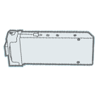
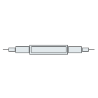
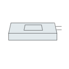
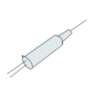
According to structure, optical devices can be divided into TO devices (TOSA, ROSA, BOSA); DIP (or Butterfly) devices; surface mount (surface mount) devices.
Difference Between Single Fiber and Double Fiber
Single-fiber module: received and sent data are transmitted on one optical fiber.
Dual-fiber module: received and sent data are transmitted on two optical fibers respectively.
The single-fiber module can save half of the optical cable resources, that is, data can be sent and received on one core optical fiber, which is very suitable in places where optical fiber resources are tight; the double-fiber module needs to occupy two optical fibers, one for transmission (TX) and one for for receiving (RX).
The common wavelengths of single-fiber modules are 1310nm and 1550nm respectively. They are used in pairs, that is, one end is 1310nm wavelength and the other end is 1550nm wavelength. They can both send and receive; while dual-fiber modules have the same wavelength, that is, both sending and receiving. Use the same wavelength. (The main difference between single-fiber bidirectional and dual-fiber bidirectional is whether the transmission and receiving wavelengths are consistent. Single-fiber bidirectional requires inconsistent wavelengths, and dual-fiber bidirectional requires consistent wavelengths).

