


Fiber Optic Tech
Overview of Common Wavelength Selective Switch (WSS) Module Implementations
Wavelength Selective Switch (WSS) is a critical component in optical communication systems, enabling wavelength selection and routing in Wavelength Division Multiplexing (WDM) networks. WSS modules separate, , and recombine light signals of different wavelengths, providing flexible wavelength management. The primary implementation methods for WSS include Micro-Electro-Mechanical Systems (MEMS), Planar Lightwave Circuit (PLC), Liquid Crystal-based (LCOS or Liquid Crystal), and other emerging technologies (e.g., silicon photonics). This article summarizes these methods and uates their advantages and disadvantages.
1. WSS Modules Based on Micro-Electro-Mechanical Systems (MEMS) Technology
MEMS-based WSS modules utilize micro-electro-mechanical systems with a micromirror array to achieve wavelength selection. Input light is dispersed into different wavelengths by a grating, and each wavelength is directed to a specific micromirror in the MEMS array. The micromirrors can tilt independently to control the reflection direction of the light, enabling wavelength selection and routing. Selected wavelengths are then recombined by the grating for output.
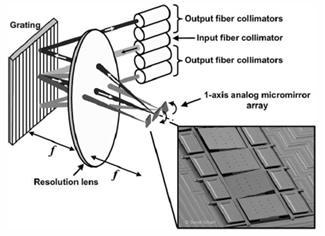
Figure 1. WSS Module Combining a Demultiplexer and MEMS Mirrors
The architecture shown in Figure 1 is one of the most widely adopted WSS module designs. It consists of a demultiplexer, a 1xN MEMS optical switch, and a wavelength remultiplexing function. The WDM signal from the input fiber is first demultiplexed by a diffraction grating, which spatially separates the wavelengths and focuses them onto the focal plane of a lens. A set of single-axis MEMS mirrors is placed at the focal plane, with each lens corresponding to a specific wavelength. By adjusting the tilt angle of each mirror, the associated wavelength can be directed to a designated output fiber.
This design features a simple structure and ease of use. In this configuration, the coupling efficiency into the output fibers depends directly on the precision of the MEMS mirror angle control. Therefore, maintaining the long-term stability and repeatability of the MEMS mirrors is the most critical challenge for this solution.
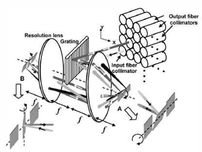
Figure 2. Schematic of a Two-Dimensional MEMS-Based WSS Module
In Figure 1, the MEMS mirrors are single-axis, allowing only linear beam steering. If the MEMS mirrors are replaced with two-axis scanning mirrors, and a two-dimensional collimator array is used, the interconnection capability of the WSS node can be easily expanded to N², as shown in Figure 2. One of the most common implementation approaches is to use a 4f imaging system, where two orthogonal one-dimensional scanners form the basis of the system.
However, the design and fabrication of a two-dimensional WSS is significantly more complex, limiting this approach mainly to academic and research institutions. At present, it is not yet practical for commercial deployment.
Currently, MEMS-based WSS products already exist. Figure 3 shows an image of a one-dimensional linear MEMS mirror array used in WSS modules.
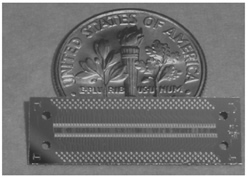
Figure 3. Photograph of a Linear Array MEMS Micromirror
2. PLC-Based WSS Modules
As mentioned earlier, MEMS technology enables a flexible structure for WSS modules, making implementation relatively straightforward. Thanks to its use of free-space optical components, MEMS-based systems can even be extended to two-dimensional mirror arrays, supporting up to N² interconnections.
Another widely discussed approach for WSS implementation is Planar Lightwave Circuit (PLC) technology. In this case, all components are integrated on a single planar chip, which naturally restricts the ability to scale to two-dimensional N² interconnections like MEMS. However, full integration brings significantly improved reliability, as it eliminates performance degradation issues such as electrostatic charge accumulation that MEMS systems may encounter. Additionally, a major drawback of MEMS-based WSS is its relatively high optical loss, whereas PLC-based devices generally offer lower insertion loss.
There are several ways to implement PLC-based WSS modules. The most common and simplest method involves microring resonator structures. As shown in Figure 4, this is a schematic of a 1x2 microring-resonator WSS module fabricated using a silicon dioxide on silicon substrate.
The working principle is as follows: A multi-wavelength signal travels through a straight waveguide that runs in close proximity to a microring waveguide. When the microring’s radius resonates with a specific wavelength, that wavelength couples into the ring, circulates, and then transfers through resonant coupling into an adjacent output channel.
Notably, Cr-based micro-heaters are placed near the resonator. By applying an electric current, the local temperature of the chip can be tuned. Through the thermo-optic effect, this changes the resonant condition of the ring, allowing the filtered wavelength to be dynamically tuned in real time. As such, this structure provides a real-time tunability similar to MEMS, aligning well with the core concept of WSS.
The switching time of a microring-based WSS is approximately a few hundred microseconds, which is significantly faster than that of MEMS-based designs. Currently, the tuning range of microring resonance typically spans a few tens of nanometers.
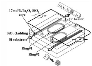
Figure 4. WSS Module Based on Microring Resonators
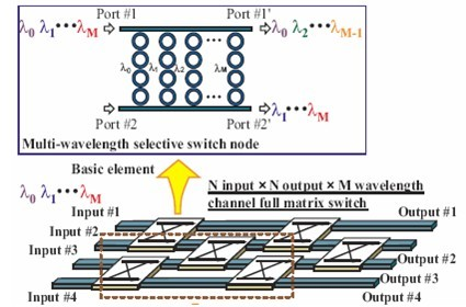
Figure 5. Schematic of an NxN Microring-Based WSS Module
Similarly, by cascading multiple microring resonators, it is possible to construct a two-dimensional NxN WSS module with multiple input and output ports. Figure 5 shows a schematic diagram of such a WSS module developed by Tokyo Institute of Technology based on this principle.
The widespread research interest in microring resonators stems primarily from their resonance-based operation, which provides a very high quality factor (Q-factor). Actual testing of the module shown in Figure 5 demonstrated an extinction ratio as high as 39.0 to 46.6 dB, with inter-band crosstalk maintained around 19.3 to 24.5 dB.
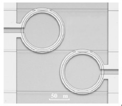
Figure 6: Practical Structure of a 1x2 Microring Optical Switch for WSS
Researchers have conducted performance tests of microring-based WSS modules in real access network scenarios. The switch used was a 1x2 microring optical switch, as shown in Figure 6. Note that the scale in the figure is in micrometers, and the total chip size is approximately 200x200μm².
In the experiment, a 10 Gbit/s NRZ signal was used. After switching through the microring, the modulation signal showed almost no distortion, and the bit error rate remained below 10~12. Compared to earlier examples, the extinction ratio in the ON and OFF states was lower—around 12 dB, but the inter-band crosstalk remained similar at about 20 dB.
This test, conducted in 2005, is considered one of the earliest and most compelling demonstrations of the practical viability of PLC-based, particularly microring-based, structures for WSS applications.
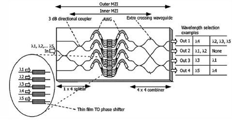
Figure 7: WSS Module Based on AWG Components
In addition to microring resonators, there are other methods for implementing WSS modules using PLC technology. One of the most representative approaches is based on Arrayed Waveguide Grating (AWG) structures. As shown in Figure 7, this architecture was proposed by NTT. The illustrated 1x4 WSS module consists of four AWGs combined with thermo-optic phase shifters.
Similar to the microring-based approach, this design utilizes the thermo-optic effect to induce phase changes, thereby altering the routing paths of different wavelengths. Compared to microring resonators, this structure appears more complex and significantly larger in size.
However, it has the clear advantage of very low optical loss—tests showed an average insertion loss of only 2.7 dB, making it highly attractive for certain applications.
3. Liquid Crystal-Based WSS
In addition to MEMS and PLC technologies, another widely used WSS implementation method is based on liquid crystal technology. Liquid Crystal-based WSS modules primarily use Liquid Crystal on Silicon (LCOS) technology. Input light is dispersed by a grating and projected onto an LCOS panel, which consists of a 2D pixel array. Each pixel modulates the phase or polarization of light via the electro-optic effect of liquid crystals, controlling the routing direction. Selected wavelengths are recombined by the grating for output. This approach is relatively simple and operates similarly to a spatial light modulator. By directing different wavelengths of light onto different pixels, the orientation of the liquid crystal molecules in each pixel can be controlled. This, in turn, modulates the polarization state of the light. A polarizer is then used to control the output intensity of each wavelength component.
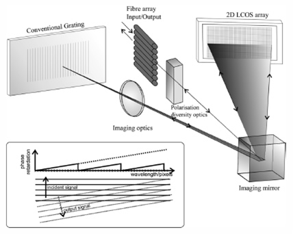
Figure 8. Operating Principle of an LCOS-Based WSS
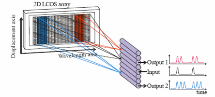
Figure 9. Schematic of Phase-Controlled Routing Using LCOS for WSS
As seen in Figure 8, the operating principle of this system is very similar to that of the MEMS-based WSS shown in Figure 1. Both systems involve input light entering through a fiber, passing through a grating-based demultiplexer, and spatially separating the different wavelengths. The key difference lies in the wavelength selection unit. In Figure 1, the direction of propagation for a specific wavelength is adjusted by independently controlling the angle of mirrors in real-time to route any wavelength along any path. In contrast, in Figure 8, the propagation direction is controlled through phase changes.
The liquid crystal spatial light modulator (SLM) can adjust the phase of a specific wavelength as needed. Importantly, all beam paths in Figure 8 are reversible. For example, light from the first fiber enters the system, and through spatial phase modulation (SLM), the phase of the other N-1 wavelengths changes in the same way. These wavelengths are reflected back, recombined, and output through the second fiber. For wavelengths requiring downlink, the phase can be adjusted differently, allowing them to be output through the third fiber, directing the signal to the downstream branch.
To better understand this process, Figure 9 provides a simplified schematic of the system, omitting elements like wavelength division multiplexers.
The recent interest in this WSS implementation is primarily due to its high flexibility. As observed, MEMS mirrors only the propagation direction of light, while the SLM in Figure 8 adjusts the optical path through phase changes. This ability to control phase not only changes the direction of light but also enables dispersion compensation through phase adjustment.
The SLM in Figure 8 uses a two-dimensional LCOS array. LCOS is one of the most widely researched liquid crystal display (LCD) technologies in recent years.
In theory, any SLM could be used for WSS, and researchers in France have proposed an interesting approach, as shown in Figure 10.
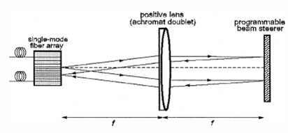
Figure 10: Schematic of WSS Principle Based on Liquid Crystal Grating
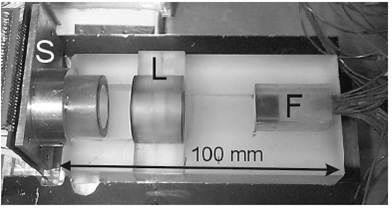
Figure 11: Photograph of a Liquid Crystal Grating-Based WSS Module
Compared to Figure 10 and Figure 8, this design is much more compact. This is because the scheme directly employs holographic technology on the liquid crystal to create a digital grating. As a result, the liquid crystal panel integrates the wavelength division multiplexing system and the spatial light modulation system into one, making the system much more compact. However, this comes at the cost of higher phase control requirements, which reduces the system’s tolerance.
Figure 11 shows a photograph of a WSS module actually fabricated based on the principle in Figure 10. In the image, S represents the SLM liquid crystal grating phase-modulating module, L is a convex lens, and F indicates the input/output fiber array. Like the design in Figure 1, this system uses spatial optical components. Although this solution is more compact than the one in Figure 8, the overall module is still several orders of magnitude larger than a PLC-based WSS. However, the liquid crystal phase modulation offers unlimited functional expansion capabilities.
4. Other WSS Technologies
In addition to the technologies mentioned above, there are several other approaches that can be used for WSS.
Silicon Photonics
Silicon photonics uses silicon-based Photonic Integrated Circuits (PIC) for WSS, employing microring resonators or Mach-Zehnder Interferometers (MZI) for wavelength selection. It offers ultra-high integration and cost potential but is less mature, with higher insertion loss and polarization dependency, limiting commercial adoption.
Bulk Grating
Bulk grating WSS uses traditional optical components (e.g., gratings and lenses) for wavelength separation and selection, combined with mechanical or electro-optic modulation for routing. This approach is low-cost but bulky and lossy, gradually being replaced by MEMS and LCOS.
Photonic Crystals
Photonic crystals use periodic refractive index structures for wavelength selection, offering ultra-miniaturization potential. However, their complex design and manufacturing challenges keep them in the research stage.
Comparision
|
Technology |
Advantages |
Disadvantages |
Applications |
|
MEMS |
High flexibility, low loss, mature technology |
Mechanical reliability issues, complex manufacturing |
High-port-count ROADM, long-haul transmission |
|
PLC |
High integration, low power, high stability |
High loss, limited port scalability |
Compact devices, short-haul networks |
|
LCOS |
High resolution, dynamic tunability, multi-port |
High cost, slow response, temperature-sensitive |
Flexible wavelength al, data centers |
|
Silicon Photonics |
Ultra-high integration, cost potential |
Immature technology, high loss |
Future high-density integrated networks |
Selection Guidance
High-Performance Needs: MEMS and LCOS are mainstream choices for high-port-count and low-loss ROADM systems. MEMS suits long-haul transmission, while LCOS excels in dynamic wavelength al.
Cost-Sensitive Scenarios: PLC’s integration and cost advantages make it suitable for small-to-medium networks or short-haul applications.
Future Outlook: Silicon photonics holds long-term potential but requires further maturation.
Each WSS implementation method has unique strengths and weaknesses, and the choice depends on application requirements (e.g., port count, loss tolerance, cost constraints). MEMS and LCOS dominate the market due to their high performance and flexibility, while PLC and silicon photonics offer advantages in specific scenarios. As optical communication demands grow, WSS technologies will continue evolving toward higher integration, lower power consumption, and greater flexibility.


