


Fiber Optic Tech
MSA 800G Optical Module - 8x100G Technology Analysis for SR Scenarios
800G Optical Module Technology Background
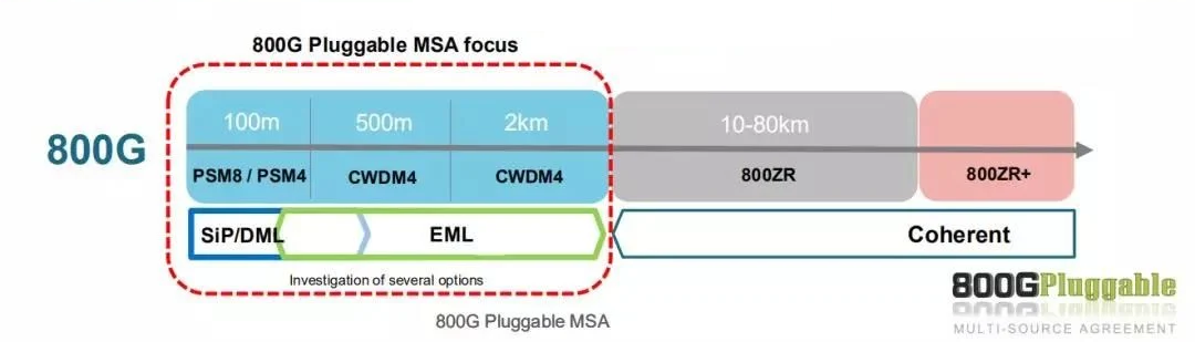
There are two main organizations for 800G optical module interface technology: the 800G Pluggable MSA working group and the QSFP-DD800 MSA. Based on the 800G technology white paper published by the 800G Pluggable MSA working group, the main application scenarios are: 8x100G solution for SR (short reach) scenarios of about 100 meters in data centers, 4x200G solution for FR (front reach) scenarios of about 2 kilometers, and 800G solution for DR (direct reach) scenarios of about 500 meters.
The current data center structure can be divided into two main types:
1. Three-layer structure of hyper-scale data centers:
Each layer has a certain convergence ratio, such as 3:1. The ZR coherent optical interconnect scheme is used to connect to other data centers above the Spine layer.
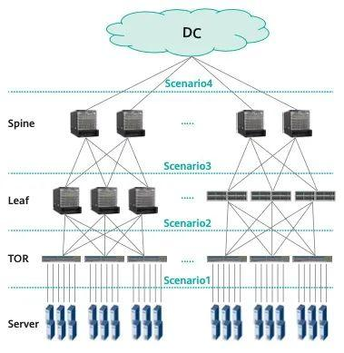
2. Two-layer structure of AI cluster data center networks: Fewer layers than the first type of network structure. No convergence between layers, which means more traffic for big data.
Each Leaf directly connects to the server interface, but the traffic interaction is much smaller.
Faster deployment speed than the first type of structure, with almost no traffic aggregation.
When do the above structures require 800G interfaces?
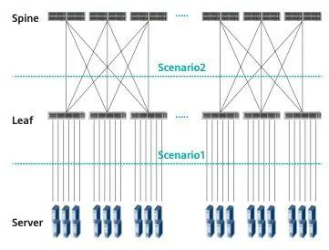
According to the white paper, In the first typical structure, if the speed between Server and TOR reaches 200G, then 800G (4x200G) is required. In the second data center structure scenario, when the traffic between Server and Leaf reaches 2x200G, 800G wideband interfaces can be used on the Leaf layer. In addition, in the above two structures, the distance from the service to the Leaf is usually 4m/20m (intra/inter-rack), from TOR to Leaf is about 60m-100m, and from Leaf to Spine is usually 500m-2km. The Spine to DCI and the interconnection between them is about 80km-120km. As mentioned at the beginning of the article, one of the problems that MSA needs to solve is the 800G interface technology for SR scenarios, namely the 8x100G technology for SR of about 100m. The other is to solve the FR and DR scenarios of 500m-2km.
8x100G Technology Analysis for SR Scenarios
The goal of MSA or related vendors is to develop low-cost 8x100G optical modules. The idea for low cost is to define a transmitter technology that achieves linear cost reduction through high integration. With the current trend of increasing switch port count and decreasing number of servers per rack, low-cost 800G S can also be used to support serial 100G server connections.
Traditional domestic data center interconnections use VCSEL multimode transmission technology with a reach of 30-50m, while MSA uses 100G PAM4 technology for single-mode fiber interconnections. It no longer uses VCSEL-based multimode solutions, but adopts parallel single-mode SMF transmission PSM8 with PAM4 modulation format (built-in DSP chip) to meet the 800G SR scenario requirements.
In order to ensure the low cost and power consumption advantages of 800G-SR8 based on single-mode SMF, MSA has defined three principles for the reasonable PMD layer standard of 800G-SR8: Multiple transmitter technologies, such as DML, EML, and Silicon Photonics (SiPh). All the potential of the devices can be fully utilized to achieve the target link performance. As long as the reliable link performance is satisfied, the parameter indicators of the PMD layer should be relaxed as much as possible.
The power budget of the SMF-based 800G-SR8 solution is similar to that defined in IEEE 400G-SR8. The difference lies in the insertion loss of the new PSM8 connector. That is, based on the current 400GE DSP ASIC and mature optical and electronic components, SR8 can be guaranteed Power budget. In addition, the biggest challenge of 800G-SR8 PMD is to find the appropriate transmitter optical modulation amplitude (OMA), extinction ratio (ER), transmitter eye diagram closure cost (TDECQ) and receiver sensitivity. The MSA working group compares the BER performance of different transmitters to find appropriate parameters for these parameters, as shown in the figure below.
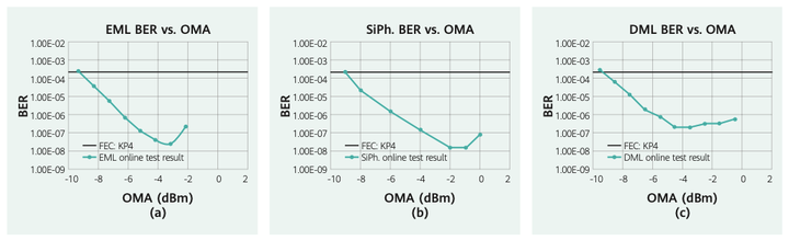
(a) BER and OMA results of the EML transmitter tested using commercial 400G DSP chips.
(b) Using a commercial 400G DSP chip to test the BER and OMA results of the SiPh transmitter.
(c) Use commercial 400G DSP chips to test the BER and OMA results of the DML transmitter.
The above comparisons are based on test results on 400G DSP chips. Among them, schemes a and b have been widely discussed. The BER performance of DML in scheme c shows that in this case, the sensitivity of OMA is comparable to that of EML and SiPh.
Considering that the transmit power of SiPh is low and the sensitivity of the three solutions is high enough, the minimum OMA requirements in 800G-SR8 can be appropriately relaxed. At the same time, considering the relatively low sensitivity requirements in SR scenarios and the power consumption limitations of 800G modules, MSA also recommends using low-complexity DSP mode. Another parameter is the bit error rate ER, which is also directly related to power consumption. Generally, as long as ER does not affect the reliability of the link, the smaller the ER, the better.
Based on the above analysis, in the 800G-SR solution, a low-cost and power-consuming solution based on SMF single mode is also feasible.


