


Fiber Optic Tech
Insertion Loss vs. Return Loss in Fiber Optical Devices & Network
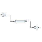
In optical fiber communication network, insertion loss (IL) and return loss (RL) are two important parameters to uate the end-to-end connection quality between some fiber components, such as fiber connectors, fiber patch cables, fiber pigtails, etc.
What is Insertion Loss
Return Loss refers to the the loss of optical power along the length of a fiber optic link due to the intervention of optical components. If the optical power is traversing at 100% into an optical component, coming out there is a loss, it is ""ribed as insertion loss and is measured in decibels (dB).
Calculation formula: IL=-10 lg(Pout /Pin)
Pout: optical power output
Pin: optical power input
The smaller the value of insertion loss, the better the performance. The difference of attenuation between fusion splicing and manual connection is generally smaller than that between fiber connectors. Suggested maximum dB loss in data center cabling:
Multi mode LC connector: max. 15dB
Single mode LC connector: max. 15dB
Multi mode MTP/MPO connector: max. 20dB
Single mode MTP/MPO connector: min. 20dB
What is Return Loss
Return loss is the measurement of the amount of light that is reflected back toward the source. When optical signals enter or leave an optical component, the discontinuity and impedance mismatch will generate reflection or echo. The power loss of the reflected or echoed signal is called return loss.
Insertion loss mainly measures the result signal value when the optic link encounters loss, while return loss is the measurement of reflected signal loss value when the optic link encounters access of components.
Calculation formula: RL=-10 lg(P0/P1)
P0: reflected optical power
P1: optical power input
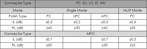
Return loss is measured in dB, usually in negative number. A high return loss is a favorable parameter and it results in a lower insertion loss. Typical range is between -15dB to -60dB. According to industry standards, UPC polished optic fiber connectors should have a return loss of over 50dB, APC over 60dB, and PC over 40dB. For multi mode optic fiber, typical return loss range between 20dB to 40dB.
Possible Causes of Poor Insertion/Return Loss
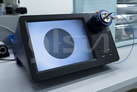
1. End face quality and cleanliness
Fiber end face defects (scratches, pits, cracks) and particle contamination will affect the connector performance and lead to poor insertion/return loss.
2. Fiber damage, misalignment and poor contact
Fiber cores need to be aligned and connected neatly and precisely with each other in order to achieve optimal performance and functionality. Sometimes damaged fiber is still able to propagate light signals, but will cause poor insertion/return loss.
3. Bend radius
Fibers are bendable, but bending too much will cause signal loss or even result in damage. If coiling fiber is required, it is suggested to keep the radius as large as possible, not exceeding 10 times that of outer jacket diameter.


