


Fiber Optic Tech
How to use OTDR Tester?
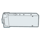
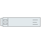
Optical Time Domain Reflectometer (OTDR) is an instrument that can understand the uniformity, defect, fracture, joint coupling and other properties of optical fiber by analyzing the measurement curve. It is made according to the principle of light backscattering and Fresnel reverse. It uses the backscattered light generated when light propagates in the optical fiber to obtain the attenuation information. It can be used to measure the optical fiber attenuation, joint loss, optical fiber fault and understand the loss distribution along the length of the optical fiber. It is an essential tool in the construction, maintenance and monitoring of optical fiber.
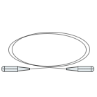
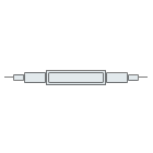
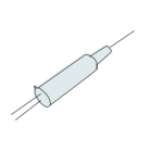
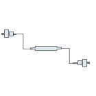
When the optical time domain reflectometer (OTDR) connects the test pigtail, firstly clean the pigtail on the test side, then the pigtail at the test socket of the vertical instrument, fully connect the convex U-shaped part of the pigtail with the concave U-shaped part of the test socket, and properly tighten it. During line maintenance or cutting connection, before connecting the tested optical fiber with OTDR, notify the maintenance personnel at the end of relay section to remove the corresponding connecting pigtail on the optical fiber distribution box to avoid damaging the optical fiber.
1. Wavelength Selection: the wavelength required for the test, with 1310nm and 1550nm for selection.
2. Distance Setting: first test the optical fiber in automatic mode, and then set the test distance according to the length of the test fiber, which is usually 1.5 times of the actual distance, mainly to avoid false reflection peak and affect the judgment.
3. Pulse Width Setting: The pulse width available for the instrument is generally 10ns, 30ns, 100ns, 300ns, 1μs, 10μs and other parameter options. The smaller the pulse width, the shorter the sampling distance and the more accurate the test. Otherwise, the longer the test distance, and the less accurate the test. The accuracy is relatively small. According to experience, parameters of 100ns and below are generally selected below 10KM, and parameters of 100ns and above are selected above 10KM.
4. Sampling Time Setting: the longer the sampling time of the meter, the smoother the curve and the more accurate the test.
5. Refractive Index Setting: according to the requirements of each transmission line.
6. Event Threshold Setting: It refers to pre-setting the attenuation of the connection point or loss point of the optical fiber during the test. When there is an event exceeding the threshold, the instrument will automatically analyze and locate it.


