Fiber Optic Tech
Core Technologies and Applications of Fiber Arrays
With the widespread adoption of 5G networks, the expansion of data centers, and the rapid development of the Internet of Things (IoT), efficient and reliable optical signal transmission technologies have become increasingly important. Fiber arrays (FA), as high-precision and high-performance optical components, are emerging as indispensable elements in fields such as optical communication, photonic integration, and laser processing.
What is a Fiber Array?
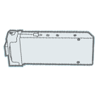
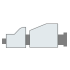
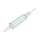
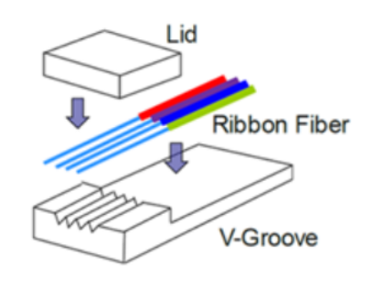
A fiber array is an optical device formed by arranging and fixing a bundle of optical fibers or ribbon fibers at specified intervals on a substrate using a V-groove base. It primarily consists of a V-groove baseplate, a cover plate, optical fibers, and adhesive. The core advantage of fiber arrays lies in their high-precision fiber alignment and low-loss optical signal transmission capability. They have become essential components in planar lightwave circuits, arrayed waveguide gratings (AWG), and micro-electromechanical systems (MEMS).
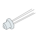
Schematic Diagram of Fiber Array (FA) Structure
Features and Advantages of Fiber Arrays
High Precision and Multi-Channel Capability
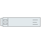
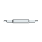
One of the most critical features of fiber arrays is their ability to encapsulate several — even dozens — of optical fibers within an extremely compact space without mutual interference. By using V-groove substrates, fiber arrays ensure precise control over fiber spacing and positioning, thereby enabling efficient optical signal coupling and transmission.
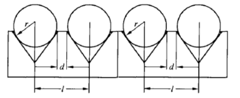
Positional Relationship Between Optical Fibers and V-Grooves
Low Insertion Loss
Through precision machining and polishing processes, the insertion loss of fiber arrays can be controlled to within 0.05 dB, significantly enhancing the efficiency of optical signal transmission.
High Return Loss
Fiber arrays typically achieve a return loss of ≥55 dB (APC), effectively reducing optical signal reflection and ensuring transmission stability.
Excellent Temperature Stability
Fiber arrays are generally made of optical fibers combined with glass substrates and cover plates. Modern adhesives on the market offer excellent mechanical and thermal stability. Like most passive optical components, fiber arrays operate reliably within a temperature range of -40°C to +85°C, making them suitable for a wide variety of harsh environments.
Simple Manufacturing Process and Versatile Structures
With continuous technological advancement, the manufacturing process for fiber arrays has become well-established. As long as precise mechanical alignment can be achieved, excellent optical performance and long-term stability are attainable. In recent years, the increasing demand for high-density optical integration has led to the development of fiber arrays with diverse structural designs. For instance, the end-face angle is no longer limited to flat or 8° slanted types — specialized angles like 42.5° have emerged to meet specific packaging requirements (e.g., for vertical coupling).
Customization
Given the wide range of devices and modules that use fiber arrays — many of which involve compact, high-density packaging — numerous product variants have been developed to meet different functional needs. These include polarization-maintaining (PM) fiber arrays, mode field conversion fiber arrays, FA+Lens combinations, and various MPO/MT to FA fan-out configurations.
Testing Methods and Performance Metrics of Fiber Arrays
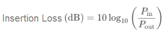
Insertion Loss (IL)
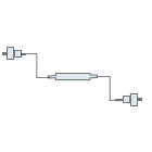
To measure insertion loss, a light source is connected to one end of the fiber array, while the output power is measured at the other end using an optical power meter. The insertion loss is then calculated based on the standard IL definition:
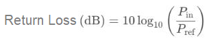
Return Loss (RL)
A return loss meter or equipment such as an OFDR (Optical Frequency Domain Reflectometer) or OTDR (Optical Time Domain Reflectometer) is connected to one end of the fiber array to measure the reflected power. Return loss is then calculated according to its standard definition:
Breakpoint or Damage Testing
Currently, the most commonly used methods include visible red light testing (using a visual fault locator) or inspection via microscope. These techniques help detect any light leakage in the fiber or waveguide path, as well as identify cracks, scratches, bubbles, or other defects on the material under high magnification.
End-Face Inspection
Specialized end-face inspection devices or microscopes are used to directly examine the polished surface of the fiber array end-face. This ensures the surface is clean and free from damage, scratches, chipping, or cracks.
For existing performance testing of fiber arrays, domestically developed distributed return loss testers (also known as OLI fiber micro-defect detectors), based on white-light interferometry, provide full distributed return loss scanning for the entire fiber array link — including jumpers, connectors, FA end-faces, and internal adhesive points. These devices offer micron-level precision (within hundreds of microns) and signal sensitivity down to -100 dB. By setting threshold values, the system can automatically detect the and signal strength of points exceeding the threshold, supporting high-efficiency mass production testing.
As a core component in optical communication and sensing systems, fiber arrays with their high precision, low loss, and excellent stability are playing an irreplaceable role in cutting-edge technologies such as 5G, data centers, and the Internet of Things. With the continuous advancement of optical communication technologies, the application scope of fiber arrays will further expand, offering broad market potential. At the same time, advanced inspection technologies, such as the OLI fiber micro-defect detector, are providing strong reliability and performance assurance, helping the industry achieve higher standards.


