


Fiber Optic Tech
Basic Knowledge of TOSA & ROSA
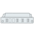
Four Parts of Transceiver
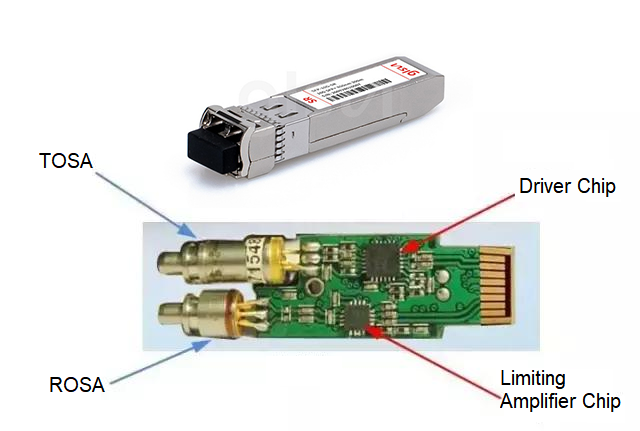
TOSA/ROSA/Driver chip/Limiting Amplifier chip, plays a different role respectively. Let's learn about the working principle and function of different components in transceiver .
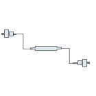
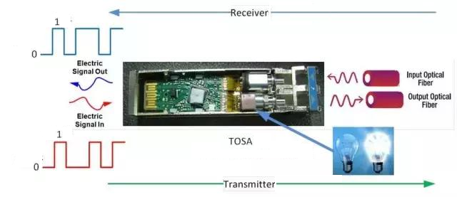
In the TX (transmitting direction), the high and low level voltage signals are converted into bright and dark light signals. In the RX (receiving direction), the light signals are converted into voltage signals and sent back.
Because the laser itself is a current-sensitive device, a laser driver is required to convert the digital voltage signal it wants to transmit into a current signal.
Laser Driver laser driver chip
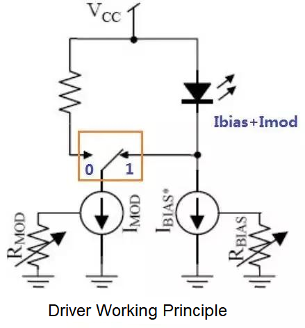
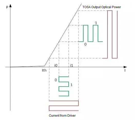
Taking a directly modulated laser as an example, there are two current sources in the Driver chip. One is the bias current source IBias to control the average optical power, and the other is the modulation current source Imod to control the extinction ratio ER. The voltage signal at the input end of the Transceiver, 0 or 1, controls the position of the switch in the picture above.
When the switch is switched to position 1, the current flowing through the laser is Ibias+Imod. The current is large, so the laser emits strong light.
When the switch is switched to position 0, the current flowing through the laser is Ibias. The current is small, so the laser emits weak light.
In this way, the conversion of the voltage signal into light intensity and light intensity is completed, thereby completing the signal modulation.
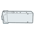
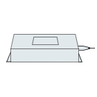
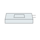
TOSA (Transmitter Optical Sub Assembly)
Emitting Optical Component
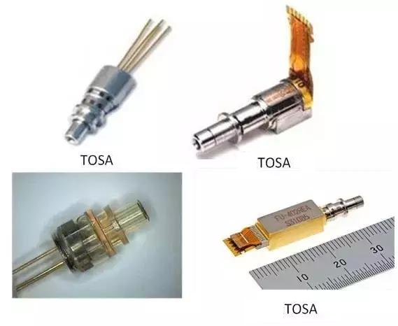
Round-TO CAN package, Square-BOX package
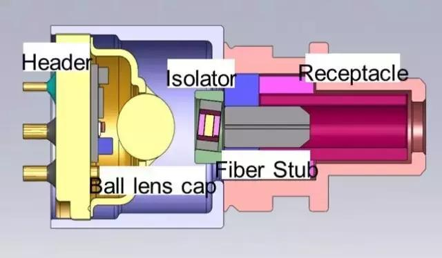
The core of TOSA is the light bulb, which is the Laser. Lasers are divided into two types
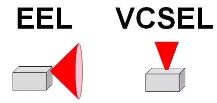
One type is long wavelength 1310nm or 1550nm edge emitting laser (Edge Emitter Laser)
One type is a short-wavelength 850nm vertical surface cavity laser (Vertical Cavity Surface Emitting Laser)
The emitted light is collimated and focused by the optical lens and then sent to the optical fiber. In order to prevent light reflection, some TOSAs also add an isolator.
For Laser, the most important thing is the PI curve. In the PI curve, we focus on two DC parameters. One is the Ith threshold current. Only when the driving current is greater than the threshold current, the laser will emit light. The other is the slope Slope. Both parameters have a strong temperature dependence, with Ith increasing as temperature increases and Slope decreasing as temperature increases.
Directly modulated laser modulation curve
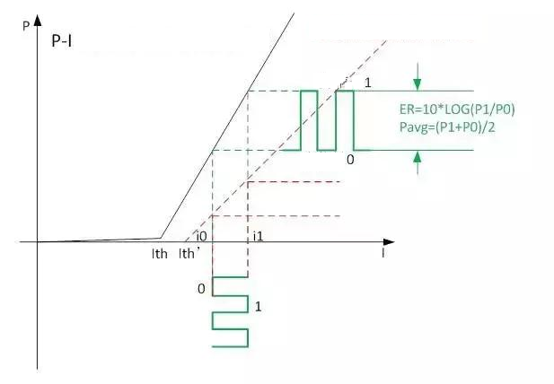
As can be seen from the above figure, as the laser temperature increases, the average optical power Pavg and extinction ratio ER will become worse after the same modulation current is input to the laser. Therefore, necessary temperature compensation needs to be done when designing the Transceiver.
The PI curve of each Laser is inconsistent, so each Transceiver needs Tuning to achieve the same performance parameters; the PI curve of the same Laser will change with temperature changes, so the same Transceiver needs to be Tuned at different temperatures. Implement temperature compensation.
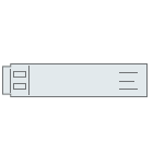
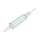
ROSA (Receiver Optical Sub Assembly)
Receive Optical Component
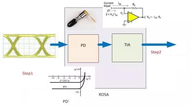
ROSA is relatively simple and contains two components, PD and TIA.
PD is Photo Detector, a photoelectric detector, which is responsible for converting the intensity of light into the magnitude of electric current. This product is basically the same thing as a solar water heater. If the weather is good and the sun is sufficient, the water will be hot. If the weather is bad, the water will be cold. PD is also divided into two types: PIN and APD. APD is an avalanche diode with higher sensitivity.
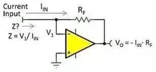
TIA is Trans-Impedance Amplifier, the abbreviation of transimpedance amplifier, which is used to convert current signals into voltage signals. Because at the Transceiver transmitting end, the signal sent is a voltage signal, so the receiving end still returns the voltage signal to others.
LA (Limiting Amplifier) limiting amplifier
The function of the limiting amplifier circuit is that when the input signal is small, the limiting amplifier is in a linear amplification working state, and the output changes linearly with the input; when the input signal reaches a certain level, the output will not change with the increase of the input signal, but will remain at a certain value. on, that is, it is in the limiting working state.


